
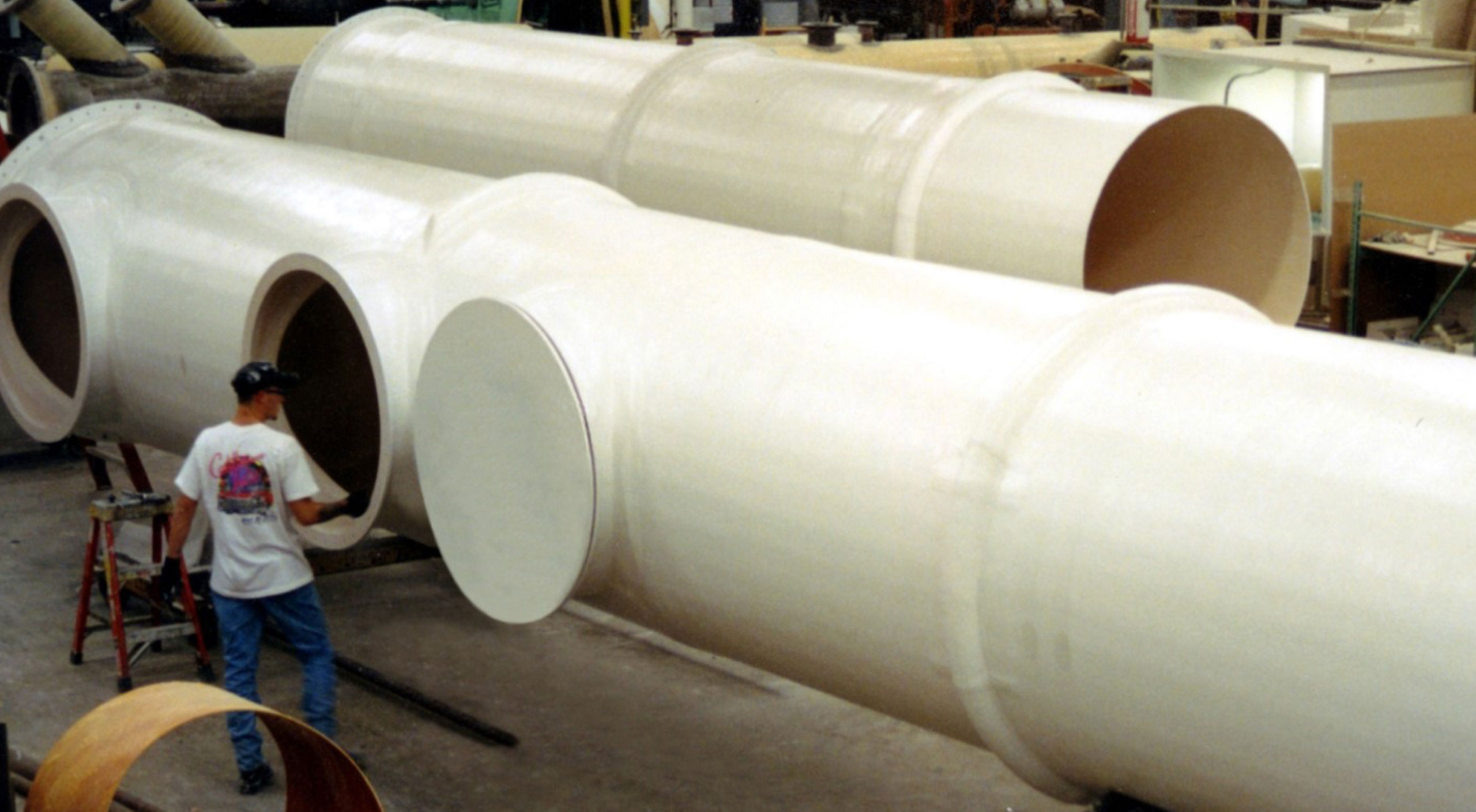
Fiberglass Reinforced Plastic Pipe
Berglass-reinforced thermoset plastic pipe (or FRP pipe) is often the material of choice for corrosive process systems. This is due to a variety of factors:
- An ability to be tailored for a wide variety of corrosion-resistant conditions
- Lightweight (less than 20% of steel, 10% of concrete)
- Excellent strength to weight (stronger than steel on an equal weight basis)
- Low coefficient of friction (>25% better than steel)
- Good dimensional stability Low thermal conductivity (saving insulation costs)
- Low long-term maintenance costs
An evaluation of the system’s total cost, including all of the above variables, often demonstrates cost savings for fiberglass FRP pipe vs. steel, with even greater cost savings over alternative alloy constructions.
Composites USA manufactures hand lay-up and filament wound FRP pipe in all commercially available resin systems, including polyester, vinyl ester, furan, phenolic, and epoxy thermoset resin systems. Resin systems, as well as reinforcements, are tailored for specific applications. FDA compliant materials are available, as are flame retardant and dual containment FRP pipe systems.
The design of any pipe system must take into account many different factors. Corrosion allowances, operating pressure, vacuum, temperature, abrasion, flammability, and electrical conductivity are just a few of the characteristics of the desired system that must be considered and addressed with the proper choice of materials for construction. Mechanical design evaluates the strength of the pipe, the requirements for supports, thermal expansion compensation, burial loads, wind, snow, and seismic considerations. Laminate analysis and, when required, finite element analysis is a part of the overall fiberglass FRP pipe design solution.
The system analysis is completed using conventional techniques, substituting appropriate physical properties for the fiberglass system specified. A typical Specification for fiberglass pipe is also available in this catalog binder.
DESIGN CONSIDERATIONS:
The process design greatly influences the fiberglass FRP pipe design. The process generally determines the required corrosion liner resin selection and thickness, the design and operating temperatures, pressures, and vacuum.
Following a determination of the above criteria, the mechanical design of the fiberglass pipe laminate structure begins. The laminate design will balance the economic benefit of various resin and reinforcement characteristics to meet the specified process design. Finally, the overall system is evaluated for proper support, thermal expansion stresses, and compliance with appropriate codes.
The following sections highlight key relationships for fiberglass FRP pipe. In the end, a life cycle cost comparison demonstrates the cost-effectiveness of fiberglass pipe vs. steel.
Process Design
Corrosion Requirements:
The anticipated concentration limits of the process stream need to be evaluated for chemical corrosion resistance at temperature. The resin manufacturer should make specific recommendations whenever possible. Fiberglass pipes are not subject to many of the corrosion problems associated with metal pipes, such as galvanic, aerobic, intergranular corrosion, or pitting.
Resin Selection:
As noted above, specific recommendations should be made whenever possible. Fairly extensive data exists for a number of resin systems, while corrosion data is relatively scarce for others. General-purpose polyester resins should usually be avoided for chemical process piping. Corrosion-grade polyesters provide an excellent value for many mildly corrosive systems. Vinyl ester resins provide additional corrosion resistance to strong oxidizing solutions while offering better mechanical strength and temperature resistance than polyesters. Extensive corrosion resistance information is available for these resins.
Furan, phenolic, and epoxy resins generally offer additional solvent and temperature resistance, sometimes sacrificing resistance to strong oxidizers. Corrosion data for these resins is generally more limited than for the polyester and vinyl esters, but they can offer significant improvements, particularly for conveying organics in acid environments. Resin catalysts and post-cure should follow the resin manufacturer’s recommendations for all the above.
Corrosion Liner Construction:
The corrosion liner refers to the inside portion of the pipe laminate including resin reinforced with a corrosion veil or veils, and chopped strand fiberglass mat. The veil(s) may be either a corrosion grade fiberglass (C-glass), or an organic veil such as polyester (Nexus), ECTFE (Halar) or graphite. An organic veil would be used in environments known to attack glass, such as sodium hydroxide, hydrofluoric acid, etc.
The veil, when cured, will vary from 0.010″ to 0.027″, at 10% to 50% reinforcement for C-glass or Halar, respectively, with polyester in between. The fiberglass chopped strand E-glass mat that backs up the veil forms the balance of the corrosion liner. This mat generally cures to 30% +/- reinforcement. The final corrosion liner may vary from as little as 0.040″ for a C-veil and one layer of 1.5oz/ft2 chopped strand mat to over 0.250″, depending upon the customer’s understanding of the corrosive properties of the fluid contained. The standard (SPI) corrosion liner is 0.100″, while many pulp and bleach manufacturers routinely use liners twice that thickness.
The corrosion liner and the allowance should be specified to avoid confusion. Some specifications allow the use of the corrosion liner to be used in calculating the required overall pipe wall thickness. Other specifications require the liner to be treated as a sacrificial corrosion allowance and not used in any pipe structural calculations for pressure and vacuum handling capability.
Temperature Requirements:
The temperature handling capability of the various resin systems depends upon the corrosive nature of the process fluid. In general, corrosion-grade isophthalic polyesters are suitable up to a temperature of approximately 120° – 170°F (50° – 75°C), while vinyl esters are suitable up to a temperature of 170°-210°F (75°-100°C). These ranges are general only. The specific system must be evaluated in light of the corrosion requirements and, later on, the mechanical requirements (supports, expansion, fatigue, etc.). Depending on the system, the Furan, phenolic, and epoxy resins may offer slightly higher temperatures.
Pressure & Vacuum:
Fiberglass pipe is easily designed to meet the system’s specific pressure or vacuum requirements. It is common to specify pipe requirements by the system’s design pressure, using multiples of 25 PSIG (i.e., 25, 50, 75, 100, 125, or 150 PSIG design). Higher pressures can be accommodated when required. Fiberglass pipe is usually designed with a factor of safety = 10 for internal pressure and a factor of safety = 5 for vacuum.
Abrasion Resistance:
Additives such as ceramic fillers can be incorporated into the fiberglass pipe corrosion liner to enhance abrasion resistance when required. These systems have been used in power plants and other services for many years. In addition to fillers, additional layers or styles of veils may be considered.
Mechanical Design
Structural Design Principles:
Due to the wide variety of available standards, there is no universal set of criteria for designing fiberglass pipes. The following equations and constants may be used in the mechanical design of fiberglass pipes. Acceptance criteria are based upon the most current revision of ASTM D-2996 (Standard Specification for Filament Wound Reinforced Thermosetting Resin Pipe):
Poisson Ratio:
The ratio of the axial strain to the hoop strain. Usually reported as 0.30 for laminates under discussion.
Density:
0.055 lb/in , or 1.5 gm/cm .
Specific Gravity: 1.5
Friction Coefficient: Surface Roughness: 150-160 (Hazen-Williams)
Surface Roughness: 1.7 x 10 ft (Darcy-Weisbach/Moody)
Internal Pressure Rating:
Based upon the hydraulic design basis for static or cyclic conditions in accordance with ASTM D-2992. The design basis is the hoop stress or strain that results in an estimated life of 100,000 hrs or 150 million cycles for static or cyclic conditions, respectively. Service factors are applied, usually 0.8 – 1.0 for cyclic and 0.50 0.56 for static conditions.
Thermal Conductivity:
- 1.0- 1.5 BTU/(ft )(hr)(°F)/inch for polyester / vinyl ester pipe. The equivalent K factor is 0.083 2 0.125 BTU/(ft )(hr)(°F).
Thermal Expansion:
The hoop and axial directions may vary. The typical axial expansion for filament-wound pipe at a 55° wind angle-5 is 1.1 – 1.5 x 10 inch/inch/°F (or approximately twice that of steel).
Thermal expansion in piping systems may be accomplished by guides, expansion loops, mechanical expansion joints, anchors, or combinations of the above. The use of these tools is similar to steel pipe design.
Fiberglass pipe has a very low modulus relative to steel (<5% of steel). This significantly improves the pipe’s ability to handle expansion and contraction loads.
There are several tables available that specify the design modulus for calculating this expansion/contraction force. Fiberglass-reinforced pipe is an anisotropic material that results in different modulus values for tensile, bending, and compression and varies again depending upon the resin, reinforcement, and reinforcement orientation used. Care must be taken to ensure the appropriate modulus is used, and a ply by ply laminate analysis is generally appropriate. An example of these tables is shown in our Pipe Specifications.
Supports and Guides:
Proper support for fiberglass pipes is very similar to steel pipe support. Several key points to consider are the following:
- Avoid point loading
- Provide the minimum support width – bearing stress < 85 psi.
- Protect against abrasion – use abrasion shields
- Support equipment and valves independent of the pipe
- Avoid unnecessary bending
- Avoid unnecessary loading in vertical runs, and support vertical runs in compression where possible
Guides should allow movement in the axial direction only. Care should be taken to provide protection at all contact points using a steel or fiberglass saddle bonded to the pipe. Anchors must restrain the pipe against all forces. Anchors break the pipe system into component systems, which are then analyzed for expansion. Pumps, valves, and other equipment can sometimes function as an anchor. Additional anchors may be required, and including them on at least 300 ft straight run intervals is good practice.
Guides and anchors function as supports. Supports are required to prevent excessive pipe deflection. For fiberglass pipe, a mid-span deflection of no greater than 0.5 inch generally results in acceptable bending stresses. If the deflection exceeds 0.5 inches, a safety factor on the bending stress of 8:1 is usually sufficient.
Buried Pipe:
Buried pipe design differs from above ground design in many respects. Most of these requirements are spelled out in Appendix A of AWWA Standard C-590-88. Additional design details will be required, including pipe size, surge pressure, working pressure, service temperature, soil conditions, soil-specific weight, depth of cover, and traffic loads. Note that while the previous discussions have used ASTM service design factors of less than or equal to 1.0, the AWWA C-950 specifies design factors that are the reciprocal of the service design factors and are always greater than or equal to 1.0.
Contact Composites USA for specific guidance in this area.
Joining Pipe:
Composites USA pipe may be assembled using either butt and wrap (fiberglass lay-up) or flanged construction. Factory subassembly is available and recommended for branch connections. The procedures for butt and wrap joining are similar to those shown for Class 1 duct, also in this catalog binder. The thickness and width of the joints will vary depending upon the system’s pressure classification and liner requirements.
Cost Comparison:
Hydraulics:
Composites USA fiberglass pipe offers significant hydraulic advantages over steel pipe for the following reasons:
- Fiberglass pipe is smoother than steel
- Fiberglass pipe stays smoother than steel
- Fiberglass pipe provides larger cross-sectional flow areas
Fiberglass pipe has a smoother internal surface than steel pipe, with a Hazen-Williams roughness coefficient of 160 when new or 150 used. On the other hand, steel pipe has a Hazen-Williams roughness coefficient of 120 when new or 65 used. The far greater loss in smoothness for the steel pipe is due to scale build-up on the steel pipe. Note that even when the fiberglass pipe is used, it is still much smoother than new steel.
Composites USA, as do many manufacturers of fiberglass pipe, provide internal diameters for their pipe and fittings which match the nominal pipe size. Thus, an 18″ diameter fiberglass pipe would have an 18″ internal diameter, while an 18″ diameter schedule 40 steel pipe would have a 16.88″ internal diameter, providing only 88% of the flow area of its fiberglass counterpart.
These key differences are directly related to substantial cost savings available with the use of fiberglass pipe as shown below.
Material Costs:
The first cost (material) purchase price of fiberglass pipe and fittings for typical installations has been variously reported as 0.75 – 2 times the price of similar diameter stainless steel pipe systems. But first cost is only one piece of information in evaluating overall system cost. An evaluation of installed plus operating cost of piping systems usually generates a compelling case for the use of fiberglass pipe.
In addition to the material purchase price, evaluation of the total system cost considers the following:
Pipe Installation Cost
- Material purchase price (advantage – usually SS)
- Support requirements (supports, anchors, expansion joints – advantage FRP)
- Joint make-up times (cutting and welding advantage FRP)
- Rigging requirements (light weight FRP vs. steel weights – advantage FRP)
Pipe Operating Cost
- Energy costs (pump horsepower requirements advantage FRP)
- Maintenance requirements (painting, repairs, descaling, etc. – advantage FRP)
Total System Life Cycle Cost
- Summarizes the above costs over the anticipated useful life of the system using discounted cash flows or similar methods to assign a time value for future cash flows (advantage FRP).
Pipe purchase cost differentials can vary widely depending upon factors such as costs of stainless steel and pipe specification requirements. It is however, fairly straight forward for the consumer to obtain pricing for comparison. The rest of the factors are somewhat less straight forward and some additional information follows.
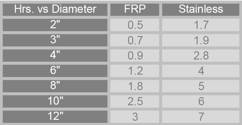
The standard method for joining Composites USA manufactured fiberglass pipe is with either flanged ends or butt and strap connections. Butt and strap is the industry method of choice for most severe corrosion services, and involves butting the fiberglass ends together and completing a wet fiberglass lay-up (strap) over the joint area. Although this is a procedure that takes skill and training to successfully complete, it is generally easier to learn than welding stainless steel.
The time required to cut, prepare and weld the two materials are as follows (budget purposes).
Operating Costs:
One of the key reasons to consider fiberglass pipe for any traditional carbon steel systems is its generally lower cost to operate, or horsepower requirements.
The discussion in the previous section called attention to the larger flow area generally available with fiberglass pipe (12% greater of the 18″ diameter example given). This is one key reason why fiberglass pipe results in lower pumping costs. A second reason is the lower coefficient of friction for fiberglass pipe, 25% lower for new systems and twice as low for aged systems.
This fact allows the system designer to choose between down sizing the line in (in fiberglass) or taking advantage of lower operating costs. These costs are usually significant and can be estimated as follows:
For the 18″ diameter pipe mentioned above, assume 6,000 gpm traveling through a 2,000 ft long straight pipe system. Costs will be estimated for one year only (year #3). The process is repeated for each year of the estimated useful life of the system. Use of the HazenWilliams relationships is used in the analysis below. Other formulas, such as the Colebrook equation may be used and should yield similar results.

Literature & Specification Sheets
- FRP Pipe Specification Sheet
- FRP Printable Brochure
Latest Technical Articles

Maximizing Cost Savings: The Impact of DualGuard FM UL Approvals
Uncover how DualGuard FM UL approvals revolutionize cost-effectiveness. Discover key insights on maximizing savings through cutting-edge technologies. Elevate your safety standards while optimizing financial efficiency.

Elevating Safety in Corrosive Environments: The Game-Changing Power of FlameGuard E84 Low Flame Ducting
Dive into the revolutionary world of FlameGuard E84 Low Flame Ducting. Uncover how this innovation reshapes safety standards in corrosive settings, ensuring optimal protection and peace of mind.

Revolutionizing Industrial Safety with DualGuard UL & FM Listed Firesafe Ducting
One of the latest innovations leading this charge is the DualGuard UL & FM Listed Firesafe Ducting from Composites USA. This advanced ducting system is designed to provide unparalleled fire safety and reliability in demanding industrial environments.